
Universal, Independent Dual System Hydraulic Test Stand Features:
1. Dual Independent Hydraulic Test System for Testing All Hydraulic Components
Such As Reducing Valves, Linear Actuators and Related Components
2. Universal Hydraulic Test Stand Hydraulic Pump and Motor Test System for
Testing All Hydraulic Pumps and Motors
STANDARD FEATURES AND SPECIFICATIONS FOR
HYDRAULIC PUMP AND MOTOR TEST SYSTEM:
· The Pump Test Stand (PTS) is Designed for Testing
All Fixed and Variable Displacement Pumps
· Precise Digital Pressure Gauges
· High Accuracy Digital Flow Meters
· Stainless Steel Pressure Supply Tank (175 Gallons)
· 5000 PSI Working Pressure
· All Gauges Enclosed in Skydrol Proof Enclosure
· Stainless Steel Construction
· Heavy Duty Work Sink with Grating
· Sink Drain Pump with Filter
· Loop Pump for Reservoir, Continuously Filters and
Cools Fluid
· High Capacity Loop Pump Filter and Pump Outlet Filter
· LED Warning Indicators for Loop Filter,
Supply Tank Low Level, and High Fluid Temperature
· Dual, Extra Capacity Water to Oil Coolers
· Automatic Oil Temp Control
· Guaranteed No Leaks, Safety Pan Completely
Covers Bottom
· Current Pressure Gauge and Flow Meter
Certificates of Calibration
VARIABLE FREQUENCY DRIVE FEATURES:
· Eaton® All Digital Variable Frequency
· Panel Mounted Controls
1. Master Switch
2. Emergency Stop Switch
3. RPM Control Switch – High Resolution Potentiometer
(0-6000 RPM Adjustable Speed)
(10,000 RPM Available)
4. Rotational Switch
· Digital Readouts
1. Panel Mounted Tachometer RPM
2. Motor Over Voltage
3. Motor Over Current
4. Motor Over Temperature
5. Ground Fault
6. Output Phase Supervision
7. Encoder Fault
STANDARD FEATURES AND SPECIFICATIONS FOR
THE DUAL INDEPENDENT HYDRAULIC TEST SYSTEM:
· Completely Independent Dual System
· Each System May be Used Independently
or Combined Together for Maximum Flows
· Will Deliver Different Pressures and Flows
Simultaneously
· Two Separate Work Stations for System A & B
· System A
1. Oilgear? Pump
2. Lincoln? Motor
3. Complete Pressure Adjustment (450 – 5000 PSI)
4. Complete Flow Adjustment (0 – Full GPM)
5. Pressure and Return Ports
6. Digital Pressure Gauges (.25% Accuracy)
7. Digital Supply and Return Flow Meters
(1% Accuracy)
8. Safety Over Pressure Relief Valve
9. By-Pass Dump Valve
10. Pump Flow Control Valve
11. Pump Pressure Control Valve
· System B
1. Oilgear? Pump
2. Lincoln? Motor
3. Complete Pressure Adjustment (450 – 5000 PSI)
4. Complete Flow Adjustment (0 – Full GPM)
5. Pressure and Return Ports
6. Digital Pressure Gauges (.25% Accuracy)
7. Digital Supply and Return Flow Meters
(1% Accuracy)
8. Safety Over Pressure Relief Valve
9. By-Pass Dump Valve
10. Pump Flow Control Valve
11. Pump Pressure Control Valve
· Five Pumps
1. Oilgear? System A Pressure Compensated Pump
2. Oilgear? System B Pressure Compensated Pump
3. S/C? High Pressure Intensifier Pump (10,000 PSI)
4. Work Sink Drain Pump
5. Reservoir Kidney Loop Pump
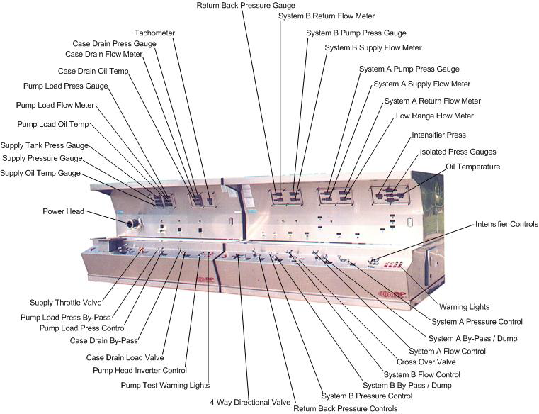
· Instrumentation – All Gauges Feature Easy
Programmability for Field Calibration
· Five Digital Flow Meters (1% Accuracy)
1. System A Pump Supply Flow
2. System B Pump Supply Flow
3. System A Return Flow
4. System B Return Flow
5. Low Range (.4 – 7 GPM)
· Seven Digital Pressure Gauges (.25% Accuracy)
1. System A Supply Pressure
2. System B Supply Pressure
3. Return Back Pressure
4. Low Independent Pressure Gauge
5. Medium Independent Pressure Gauge
6. High Independent Pressure Gauge
7. Intensifier Pressure Gauge
· Air Over Oil Intensifier
1. Digital Pressure Gauge (.25% Accuracy)
2. Air Shut-Off Valve
3. Air Regulator
4. Safety Over Pressure Relief Valve
5. By-Pass Dump Valve
6. Dedicated Port
· Safety Features
1. Two Ergonomically Located Emergency
Stop Switches
2. Safety Over Pressure Relief Valves for both
System A and B
3. Safety Drip Pan Completely Covers Bottom
to Ensure Clean Floors
4. All Electrical Components Installed in
NEMA 4, 12 Enclosure
5. All Gauges are Fully Enclosed in NEMA 4. 12
Enclosure with a Clear Front Safety Glass Cover
6. Operational LED Warning Indicator Lights
7. Dual Heavy Duty Floor Locks to Ensure Stability
8. Optional Safety Glass Sliding Doors for Work
Sink
· Super Clean Filtration – Industry Leading
Filtration Ensures Quality While Increasing
Aircraft Component Life
· System A & B High Efficiency, Non-Bypass
Pressure Filters (3 Micron Absolute)
· Reservoir Kidney Loop Filter (3 Micron Absolute)
· Sink Drain Filter (3 Micron Absolute)
· Reservoir Fill Pump Filter (3 Micron Absolute)
· 4-Way Directional Flow Control Valve
Manually Operated 4-Way Directional Flow
Control Valve with Complete Flow Control
to Either Port A or Port B
· Hedland? Digital Low Flow Return Meter with
Electric Selector Valve for Testing Internal Leakage
of Components (.4 - 7 GPM Standard)
· Operational Warning Lights
1. System A & B Pressure Filter Condition
LED Warning Indicator for Clogged Conditions
2. Kidney Loop Pump Filter Condition
LED Warning Indicator for Clogged Conditions
3. Reservoir Low Level LED Warning Indicator
4. High Fluid Temperature LED Warning
Indicator
· 3 Each Stand Alone Noshock? Pressure
Gauges (.25% Accuracy)
* Suggested Ranges 0-60 PSI, 0-1000 PSI,
0-7500 PSI
· Over Pressure Gauge Savers on All Gauges
· Reservoir Kidney Loop Pump
· Continuously Filters Fluid
· Continuously Cools Fluid
· Automatic Oil Temperature Control
· Panel Mounted Oil Temperature Set Point
· Digital Oil Temperature Gauge
· Return Back Pressure for Dynamically
Loading Components
· Return Back Pressure By-Pass Valve
· Return Back Pressure, Pressure Adjustment
Valve
· Return Back Pressure, Pressure Gauge
· Return Back Pressure Flow Meter
· Additional Features
· All Welded, 14 Gauge B3 (Brushed Finish)
Stainless Steel Cabinet
· Illuminated Work Area Provided
By Overhead Sink Light
· Test Port for all Pressure Gauges
· Easy Access Exterior Fluid Sampling
Valve to Meet Quality Parameters
· Safety Drip Pan Completely Covers Bottom
· Work Sink with Perforated Metal Grating
· Heavy Duty All Welded 1/4" Think Wall Tubing Frame
with Fork Lift Brackets
· Easy Maneuvering Ensured by Two Fixed and
Two Swivel Castors with Stability Provided by
the Heavy Duty Floor Lock
· Work Sink Drain Pump with Filter (4 GPM)
· Durable Laser Engraved, Aluminum Placards
· Panel Mounted Operational Instructions
· Current Pressure Gauge and Flow Meter
Certificates of Calibration
STANDARD FEATURES AND SPECIFICATIONS FOR
HYDRAULIC PUMP AND MOTOR TEST SYSTEM:
· Supply Port
1. Digital Supply Pressure Gauge
(.25% Accuracy)
2. Supply Throttle
3. Supply Pressure Adjustment (0-200 PSI)
4. Digital Oil Temperature Gauge
5. Automatic Supply Pressure Control
6. Precise Supply Pressure Regulator
· Pressure Port
1. Load Valve
2. By-Pass Dump Valve
3. Digital Pressure Gauge
(.25% Accuracy - 0-5000 PSI)
4. Digital Oil Temperature Gauge
5. Digital High Pressure Flow Meter
(1% Accuracy)
· Case Drain Port
1. Load Valve
2. By-Pass Dump Valve
3. Digital Pressure Gauge
(.25% Accuracy - 0-600 PSI)
4. Digital Oil Temperature Gauge
5. Digital Flow Meter
(.4 - 7 GPM - 1% Accuracy)
6. Case Drain Sump Tank
Allows Pressure Adjustment from
(0-200 PSI)
· Super Clean Filtration – Industry Leading
Filtration Ensures Quality While Increasing
Aircraft Component Life
· Pump Outlet Filter
· Supply Port Filter
· Loop Pump Filter with LED Filter Condition
Warning Indicator
· Supply Tank Desiccant Filter
· Sump Tank Filter
· Instrumentation – All Gauges Feature Easy
Programmability for Field Calibration
· Two Digital Flow Meters (1% Accuracy)
1. Pump Flow Outlet
(Refer Model Number for Flow Range)
2. Case Drain Flow (.4 – 7 GPM)
· Four Digital Pressure Gauges (.25% Accuracy)
1. Supply Tank Pressure (0 - 200 PSI)
2. Supply Port Pressure (0 - 200 PSI)
3. Pump Outlet Pressure (0 – 5000 PSI)
4. Case Drain Pressure (0 – 200 PSI)
· Oil Temperature Control - Two Extra Capacity
Oil Coolers to Ensure 100% Duty Cycle
1. Extra Capacity Pump Outlet Load Valve Oil Cooler
2. Loop Pump Oil Cooler That Will Continuously
Cool Fluid
· Safety Features
1. Ergonomically Located Emergency
Stop Switch
2. Safety Over Pressure Relief Valve
3. Safety Drip Pan Completely Covers Bottom
to Ensure Clean Floors
4. All Electrical Components Installed in
NEMA 4, 12 Enclosure
5. All Gauges are Fully Enclosed in NEMA 4. 12
Enclosure with a Clear Front Safety Glass Cover
6. Operational LED Warning Indicator Lights
7. Dual Heavy Duty Floor Locks to Ensure Stability
8. Optional Safety Glass Sliding Doors for Work
Sink
9. Supply Tank Over Pressure Relief Valve

武汉伟祺机电工程有限公司
武汉市伟祺机械设备制造有限公司